

Metrology Concepts:
Business’ Impact on Metrology
The traceability chain is often regarded as a one-way street in which the top echelon in this chain sets the stage for the measurements that follow in the chain. However, at each level there are expectations and assumptions that are established, sometimes non-verbally, between the customer and the service provider.
Every level of the traceability chain has a customer and a supplier. This paper will evaluate both sides of this partnership: the customer’s decision-making process and how that sets the expectation for what is to be accomplished in a calibration lab; and the calibration lab’s capabilities and understanding of the customer’s requirements. Two models of instruments will be used as examples of the need to communicate from customer to supplier and vice versa.
This paper sets the stage for a theme that is continuous among three related papers, which will be presented sequentially. The second paper covers Metrology’s Impact on the Process (i.e., how the customer will use the technical calibration information in their process), presented by Jeremy Sims, while the third paper will discuss Metrology’s Impact on Business (i.e., how calibration results affect the customer’s quality and financial decisions), presented by Phil Mistretta.
The information provided in these three papers will benefit conference attendees by providing practical information and exploring the inter-relationships between Business Decisions, Metrology Practice, and Process Impact.
1. The Supplier-Client Relationship
1.1 Establishing Calibration Expectations
In many processes, from manufacturing operations to services that are provided, test and measurement instruments are used to make quantitative, and sometimes qualitative, decisions about the process. This implies that there is some level of accuracy required for these quantitative or qualitative measurements. Whether for an automotive manufacturer, a testing lab, or some other process owner, the stage is set for the expectation from a calibration service provider (CSP) once the instrumentation has been purchased for the process in which it will be used. This expectation is not always obvious, so let’s look at the natural sequence of events that results in setting the process owner’s expectation for calibration.
Someone in the organization that owns the process has determined that the process to be measured requires an instrument of some greater accuracy. This establishes the need for the test instrument that will be purchased for the process measurement. That need is met by researching instruments that are available on the market and acquiring the one(s) that fit the application. So, there is an unspoken agreement between the original equipment manufacturer (OEM) and their client (the process owner) who agrees that the published accuracy specification meets their process needs. This agreement is confirmed by the acquisition of the instrument. Note that the term ‘acquisition process’ is used to denote that this may not be the purchase of a new instrument from the OEM or one of their distributors. Indeed, it may be a purchase of a used instrument through one of several means. But, in the end, this is still an unspoken agreement between the OEM, who set the accuracy specs, and the client, who nonverbally agrees that the instrument’s original design fulfills their process measurement needs.
1.2 Fulfilling Calibration Expectations
Following this initial transaction, any CSP that supports the maintenance of the instrument (through calibration, repair, etc.) has an obligation to respect and preserve this non-verbal agreement to maintain the instrument so that it continues to meet its original level of expectation. Why you might ask? Because the process owner (the CSP’s client) has built their quality system around the tolerance limits within which the instrument is expected to perform throughout its calibration cycle.
Note that the cal cycle (i.e., the length of time that the instrument can drift) is tied to the accuracy specifications (i.e., the quantitative limits within which this allowable drift is expected to occur). It can justifiably be reasoned that the calibration cycle should be included as part of the instrument’s performance specifications. Some OEMs state their accuracy specs for multiple calibration intervals (e.g., Agilent Technologies 3458A Multimeter [1] or Fluke 5520A Multi-Product Calibrator [2]) because they understand that their many clients have differing needs for the accuracy that the instrument will maintain, and therefore differing cal intervals are needed (and vice versa). Other OEMs never state a recommended calibration interval, which leaves this to their client’s best-educated guess. In this situation, if the instrument’s performance is trended over time an adequate cal interval can be determined. But if no initial cycle is recommended by the manufacturer (who should know best how long their instrument will hold its tolerances) then at what initial interval should the instrument be recalibrated? If this instrument is a mechanical item, then it really is more dependent on the amount of use than on a specific period. Most electrical instruments are time dependent rather than usage-rate dependent. The bottom line is that the OEM should be able to give their client a clue as to a good starting interval within which their instrument will maintain its accuracy.
In this regard, as the default level of service all CSPs should perform calibration of instrumentation against the OEM specifications and should also replicate the functions, ranges, and test points recommended by the OEM, if available (but that topic will be left for another paper, as some OEMs do a good job at this while others are dismal, at best). As another feature of their service all CSPs, whether internal labs serving the client, third party providers, or the OEM, should allow for deviations from this default service as the customer requires. It is quite possible that the client has applied the instrument in a different way than the OEM originally intended. This, or other factors, can change the assumed expectation of calibrating to OEM specs. However, any deviation from the natural assumption of how the unit performs should also be annotated on the calibration label and certificate to indicate this change of expectation for the instrument’s performance. Typically, this is addressed by a limited calibration label to protect the quality system in which the instrument may be used to quantify or qualify a process.
Why ‘limited cal’, you ask? Again, following the natural sequence of events, anyone (within the organization where the instrument is used) who needs to use the instrument in another process will usually refer to the OEM’s published specifications to determine whether the instrument meets their process needs. Combine this with a valid calibration label, and the natural assumption is that the instrument will meet its stated tolerances and can be used to quantify or qualify the process – that is unless there is a mechanism in place to identify that this expectation of a full cal to OEM specs is not being met. This illustrates a problem that quite often exists within the process owner’s organization. Each user of the instrument may have a different expectation about what the calibration process should provide. One process owner may assume calibration against OEM specs, while another may assume that the instrument will be tied to a single process and requires that only certain functions of the instrument are calibrated to meet that process need. This process owner may believe that the instrument will never be moved to another process within the organization. The truth is they don’t know what they don’t know. If they leave their position and someone else takes their place, was this critical information passed on to the new employee? Has the instrument ever been used temporarily without their knowledge, perhaps on a different shift or while they were on vacation? To ensure this risk is minimized in their quality system, the most conservative action is to communicate to the CSP and to others within the process owner’s organization the expectation for calibration and any deviations from the OEM’s original design. Subsequently, the CSP has an obligation to identify any deviations of the instrument from the OEM’s original design back to the client (even if this change of expectation was communicated and a deviation approved) in the spirit of helping the client to protect their quality system from unanticipated changes in personnel or instrument usage.
The fundamental point is that all calibration clients have some assumption about the service that will be applied to their instruments when purchasing a calibration service and, if those assumptions are not stated explicitly, there may be a misalignment between what the client expects and what is provided by the CSP. By having a default service for calibration against OEM specs, CSP’s will meet much of their clients’ needs since this is typically the requirement that results from the natural sequence of events in the instrumentation acquisition process. And, to be certain that all their clients’ needs are met, there should be a rigorous communications process at the start of each transaction to ensure that the CSP fulfills each client’s specific calibration requirements while still communicating deviations from the instrument’s original design, as most will assume a cal label without warning naturally implies the instrument meets OEM specs. In this way, the client is content because they get what is expected (not just assumed) from the CSP, and the CSP is pleased because they can maintain satisfied clients.
And, by the way, it just so happens that ISO 17025[3], section 4.4 Review of requests, tenders, and contracts establishes the requirement to understand and document the customer’s expectation for calibration. Laboratories that are not accredited to ISO 17025 may or may not follow this practice but, for the reasons stated above, all CSPs should follow this good business practice. For those process owners in the market for a CSP, external auditing to ISO 17025 by an ILAC-MRA accrediting body (AB) assures this practice is taking place, among many other assurances that proper accreditation to ISO 17025 provides.
Now let’s look at a couple of examples to see how the establishment and fulfillment of calibration expectations are met or can be missed without this practice in place.
2. Illustrative Examples
2.1 Mechanical Example
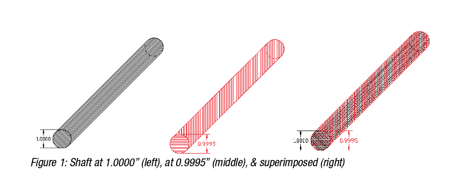
A manufacturer has a process in which a simple shaft is being produced (fig. 1). The diameter of the shaft is 1 inch (25.4 mm). For this shaft to fit into its mating part, it must have a diameter no larger than 1.0000 inch so that it will fit snugly and no smaller than 0.9995 inch (25.3873 mm) so that it will not fall out. In terms of tolerance limits, this is written as 1.0000” + 0.0000”/-0.0005” (25.4 mm +0.0000 mm/-0.0127 mm).
2.1.1 Process Testing Requirements
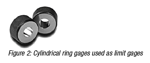
To test this, part, a manufacturing engineer determines that a cylindrical ring gage can be used. To make the part checking process simple and efficient, she selects a set of limit gages (Go and No-Go rings), such as the ones shown in fig. 2.
2.1.1.1 “Go” Test
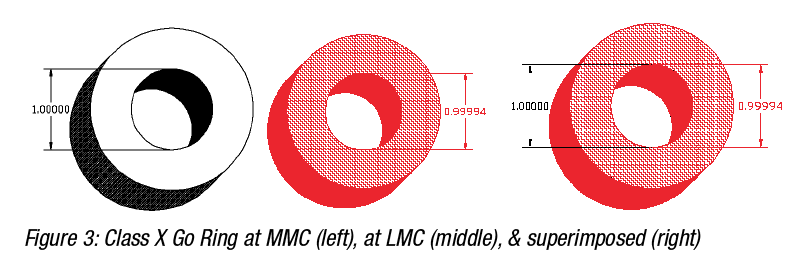
The Go ring is an ASME B89.1.6[4] class X gage (fig. 3), which has a unilateral tolerance of minus 0.000060”, or -60 µin. In other words, the tolerance limits on this gage are [0.99994, 1.00000]. These Go gages are typically manufactured to the maximum material condition (MMC or, i.e., the smaller size hole) because it is anticipated that a Go gage will fit on the part being checked, and that causes wear on the gage over time. So, with this expectation in mind, the manufacturers of these gages make it possible to use the gage for a period before it wears to its nominal size (least material condition, LMC, or ) since the users of these gages do not want to pass product that is larger than the Go diameter.
At its onset, a newly manufactured Go ring gage will reject a small amount of ‘good’ parts that are near the upper tolerance of the part. As the Go ring gage wears over time, the number of ‘good’ parts being rejected will diminish. As an example of this, if the actual value of the Go gage is 0.99994, any ‘good’ shaft with a diameter larger than 0.99950 and less than 0.99994 will ‘pass through’ the ring and will be accepted as being the right diameter shaft. But, those ‘good’ shafts with a diameter larger than 0.99994 and less than or equal to 1.00000 will be rejected as being too large when these should not have been rejected. Of course, any ‘bad’ shaft with a diameter greater than 1.00000 will also be rejected, as they should. As the Go gage wears from parts that ‘pass through’ the ring, the hole in the gage will eventually become larger and fewer ‘good’ shafts will be rejected. Once the Go gage exceeds it upper tolerance of 1.00000 (determined during its recalibration), it will be rejected and perhaps replaced or possibly downgraded to a lesser gage class.
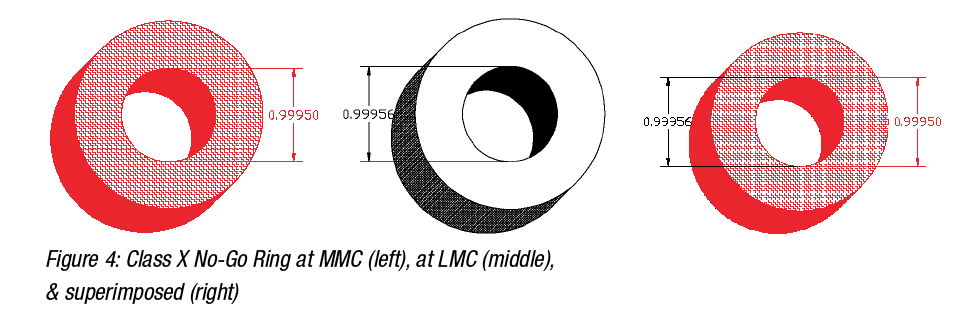
2.1.1.2 “No-Go” Test
The No-Go ring is also an ASME B89.1.6 class X gage (fig. 4), which has a unilateral tolerance of plus 0.000060”, or +60 µin. In other words, the tolerance limits on this gage are [0.99950, 0.99956]. These No-Go gages are typically manufactured to the MMC because it is anticipated that a No-Go gage is not expected to fit on the part being checked. The few parts that fail to meet their minimum tolerance and ‘pass through’ this ring will cause wear on the gage over time. Obviously, it should take much longer for the No-Go gage to wear (as long as the manufacturing process of the part being tested with this set of gages is centered and has a small variance) than it will for the Go gage. But, eventually, as this wear increases the size of the No-Go gage, larger and larger diameter shafts will be able to ‘pass through’ the ring. So, with this expectation in mind, the manufacturers of these gages make it possible to use the gage for a period of time before it wears to its largest allowable size (LMC) since the users of these gages do not want to pass product that is smaller than the No-Go diameter.
At its onset, a newly manufactured No-Go ring gage will accept all good parts that are near the lower tolerance of the part but that do not exceed their lower limit. However, as the No-Go gage wears, it will begin to reject good parts that are near their lower tolerance limit. As an example of this, the initial value of the No-Go gage is 0.99950. Any shaft that is larger than this will not fit and will ‘pass’ this No-Go test. Any shaft that is smaller than 0.99950 will ‘pass through’ the ring and will be rejected for being too small in diameter. As the No-Go gage wears and approaches is upper tolerance of 0.99956, any ‘good’ shaft with a diameter between 0.99950 and 0.99955 will ‘pass through’ the ring and be rejected as being too small when these should not have been rejected. Of course, any ‘bad’ shaft with a diameter smaller than 0.99950 will also ‘pass through’ the ring and be rejected, as they should. Once the No-Go gage exceeds it tolerance (determined during its recalibration), it will be rejected and perhaps replaced or downgraded to a lesser gage class.
2.1.2 Calibration Expectation
The process owner requires these Go/No-Go rings to be calibrated. The gages are clearly marked with the nominal diameter size, class, and type of limit gage (i.e., Go or No-Go). However, the methodology is never discussed between the CSP and their client. The client has an expectation based on a previous discussion during the initial purchase with the OEM that the gage is manufactured and tested to ASME B89.1.6 and that the calibration certificate will indicate a single value for each ring’s diameter and will include a statement of compliance indicating that the ring passes calibration. When it comes to recalibrating these gages, this expectation is not discussed with the process owner’s CSP, who is the supplier that handles calibration of their equipment inventory. Without further thought, the client assumes that this same calibration process will take place regardless of who provides the cal.
There are a couple of points to be made here about assumptions that were made. First, it is by mere chance that the CSP knows the tolerance against which the rings are to be calibrated since this was not discussed with the client and it just so happened that the class was marked on the rings. Some manufacturers of these rings that do not stamp the class value on the ring. Certainly, it is always clearly understood by the process owner (at least the one that made the purchase) as to what class of ring was purchased. But it may not be clear to everyone else involved in calibrating or using the ring as to what tolerance the ring was originally manufactured. If this is not clearly indicated, then the process owner’s quality is at an elevated risk.
The second point to be made is that the expectation of a single diameter value for each ring is not realistic, at least not after the gage has been in use. The use of mechanical devices implies that these devices will wear as they are used. The wear on the instrument is not likely to be evenly distributed across or around all surfaces. Therefore, it should be anticipated that the gage will wear unevenly and will become, in the case of a ring gage, out-of-round. An out-of-round condition indicates multiple diameters, which begs the question: which diameter should be reported to the client and when does the gage fail? Should a ‘best fit’ be approximated (fig.4, dotted blue line) to determine the pass/fail criteria? Or is it simply the ‘worst case’ (fig.4, green or red line) that determines this? The inscribed red line indicates the largest size shaft that could pass through this (exaggerated) out-of-round ring gage. ASME B89.1.6 checks for roundness, but only if the gage is a diameter master. Limit gages, such as the ones described in this example, “. . . shall be evaluated by criteria applicable to the intended use, . . .”, which simply underscores the importance of the discussion of calibration expectations between the process owner and the CSP.
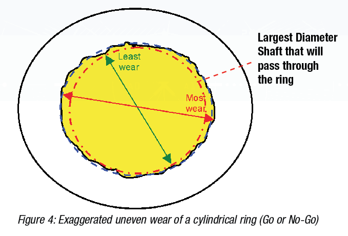
Hundreds or even thousands of data points can be taken using a vision system to generate a best fit line, but that only applies to the outer edge of the ring (front and back) but does not address the middle plane of the gage. In addition, the application of the ring must be considered in order to determine whether or not this is a useful calibration result. In this example, since the manufacturing process intends to pass product based on the Go ring diameter, then it follows that a shaft that is manufactured to be ‘round’ would pass through only if its diameter is the size of the smallest diameter of the worn ring (least wear in figure 4) or smaller. The manufacturing process intends to reject gages that are larger than this or which are small enough to pass through the No-Go ring (again, smaller than the least wear in figure 4). There are additional ‘non-mandatory’ measurements in Appendix A of the B89 spec that can be included in the requirement for calibration if this is identified as being critical to the production process (and obviously at an additional cost to the client).
The next paper in this series will investigate the effect of the actual calibration results of these limit gages on the process requirements for this example.
2.2 Electrical Example
A manufacturer has a process in which hydraulic cutting machines are regulated using embedded pressure transducers. These transducers are connected to panel meters as a means of monitoring the 4-20 mA current loop. The output of the panel meters connects to control valves, alarms, and safety shutoff valves to control the process, should it exceed system parameters.
2.2.1 Process Testing Requirements
Obviously, the pressure transducers are calibrated at regularly scheduled intervals, however, we will focus strictly on the panel meters for this example. These are Hoyt model DMS-20PC-4/20[5] panel meters, which are calibrated annually by the process owner using a Fluke 715 Volt/mA Calibrator [6].
2.2.2 Calibration Expectation
The 715 calibrator is submitted for cal and no mention is made of requirements, as the natural assumption is that the instrument will be calibrated against the OEM specs. The calibration service provider (CSP) uses an Agilent 3458A 8.5-digit multimeter to calibrate the current sourcing function of the 715. This results in Test Uncertainty Ratio (TUR) values ranging as low as 2.9:1 at the 24-mA test point and as high as 3.8:1 at the 8mA test point. The CSP reports these TUR values on the certificate which, per the CSP’s quality policy, fulfills their obligation to their clients if not stated otherwise by the client. ISO 17025 does not have an explicit requirement to provide uncertainties to the client, although section 5.10.3.1 c) states a “where applicable” clause and cites a few examples when uncertainty needs to be included in the test report. However, ISO 17025 does require an accredited lab to know their measurement uncertainty and that they understand and meet the customer’s requirements under section 4.4. In this example, the lab failed to clearly understand that the client requires a minimum of 4:1 TUR for all measurements in the calibration of their instrumentation, per the client’s quality SOPs. Not one of the current sourcing test points met this client requirement. This misalignment of expectations was caused by lack of communication between the client and the CSP. Again, the next paper in this series will investigate the effect of these calibration results on the process requirements for this example.
3. Summary
There is a natural flow to the events that indirectly establish expectations for how an instrument should perform. This begins with the OEM in the design of the instrument and the creation of the instrument’s performance specifications. It continues with the acquisition of the instrument for an intended application in a manufacturing or testing process. Many assumptions then take place when the instrument is submitted for cal. Because people tend to make assumptions and do not explicitly state their requirements, misalignment of expectations can occur due to lack of communication between the client and the CSP. These assumptions can wreak havoc on the quality of the process, sometimes without anyone being the wiser that this is a root cause of manufacturing issues. To sustain the quality of the client’s process, it is in their best interest to ensure requirements are understood by the CSP and not just arbitrarily assumed. However, for the CSP to sustain customers (and therefore revenue) it is in the CSP’s best interest to ensure the client’s requirements are clearly understood and met. For these reasons, this is both a good business practice and a requirement of ISO 17025.
The effect of assumptions throughout a manufacturing process is addressed in the subsequent paper in this series: Metrology’s Impact on the Process, which is followed by the tertiary paper in this series: Metrology’s Impact on Business.
References
- Agilent Technologies, 3458A Multimeter User’s Guide, Manual Part Number: 03458-90014, Appendix A: Specifications
- Fluke, 5520A Multi-Product Calibrator Service Manual, PN 802303, Section 1-8. Specifications
- International Standard ANS/ISO/IEC 17025, General requirements for the competence of testing and calibration laboratories
- American Society of Mechanical Engineers B89.1.6-2002 Measurement of Plain Internal Diameters for Use as Master Rings and Ring Gages
- Datel: a C&D Technologies Company; Hoyt Electrical Instrument Works, Inc., DMS-20PC-4/20 Panel Meter, MPM_DMS-20PC-4/20_E00
- Fluke, 715 Volt/mA Calibrator Technical Data, 2574106 D-EN-N Rev A
About the Speaker
Howard Zion is the Director of Technical Operations for Transcat, Inc. He holds a B.S. in Engineering Technology and a M.S. in Industrial Engineering & Management Systems from the University of Central Florida.
Howard has collected a wealth of knowledge in many disciplines during the span of 25 years in Metrology, and has been employed with:
- The United States Air Force (Strategic Air Command - PMEL)
- Lockheed Martin (Electronics and Missile Systems – Calibration Labs)
- NASA-Kennedy Space Center (Standards & Calibration Laboratories)
- Philips Electronics (Broadband Networks – Metrology/Test Engineering Operations)
- Transcat, Inc. (Corporate Office)
Mr. Zion performs additional duties in various communities, serving in the following roles:
- Two NCSLI Working Groups (163.1 & 164.1)
- Advisory board at the University of North Carolina at Charlotte (UNCC)
- Sponsor for Engineering Capstone projects at the Rochester Institute of Technology (RIT)
- Author of white papers on measurement uncertainty and business processes related to Metrology
- Investor Advisory Board with Charles Schwab & Co.
Transcat sells and markets test and measurement instrumentation as well as trusted and convenient Metrology services (including accredited calibration, repair, accredited reference standards services, managed services, 3D Metrology, and managed operations) to a variety of industries including medical device manufacturers, pharmaceutical, biotech engineering, petroleum refining, chemical manufacturing, and public utility.