Liquid manometers, because of inherent accuracy and simplicity, have applications in every industry and laboratory. They are unique in being both basic pressure measurement instruments and standards for calibration of other instruments. Despite their simplicity and wide useage, their principle of operation, the advantages of various types and the basic accuracy factors associated with them are not known by all.
The manometer has many advantages in this age of technology. Containing no mechanical moving parts, needing nothing but the simplest of measurements, the primary standard manometer is readily available at modest cost. The principle of the manometer has not changed since its inception, however great strides have been made in its arrangement and the application of the instrument to various industrial measurement requirements. Whereas formerly the manometer was considered a laboratory instrument, today we find the manometer commonly used to measure pressures ranging from as high as 600 inches of mercury to space vacuums.
The manometer utilizes the hydrostatic (standing liquid) balance principle wherein a pressure is measured by the height of the liquid it will support. For example, the weight of a column of mercury at 0 deg C that is one inch high and one inch in cross sectional area is .4892 pounds. Thus we can say that a column of mercury one inch high imposes a force of .4892 pounds per square inch or .4892 PSI.
Transcat offers calibration services for manometers throughout our network of nationwide accredited calibration laboratories. No matter your process, application, or manometer type, we can ensure that your measurements are reliable and accurate.
U Type Manometers
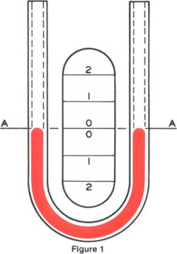
The manometer principle is most easily demonstrated in the U-type manometer illustrated in Figure 1. Here, with both legs of the instrument open to atmosphere or subjected to the same pressure, gravity forces the surfaces of the liquid to be at exactly the same level or reference zero.
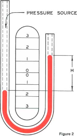
As illustrated in Figure 2, if a pressure is applied to the left side of the instrument the applied pressure depresses the fluid in the left leg and raises it in the right until the unit weight of the fluid as indicated by "H" exactly balances the pressure. Thus, if the fluid in one side stands two inches higher than the fluid in the other, and the fluid is mercury, the pressure balanced is 2x.4892 or .9784 PSI.
Note that only the height of the fluid from the surface in one tube to the surface in the other is the actual height fluid opposing and balancing the pressure. This is true regardless of the shape or size of the tubes. If the tubes are unsymmetrical, more or less fluid may be moved from one to the other, but the height of fluid required to obtain equilibrium is independent of all but the fluid density and vertical height.
Table 1 shows the equivalent values for various common indicating fluids at 71.6 Deg F or 22 Deg C and demonstrates the versatility of the manometer. When using water as the indicating fluid, a 10" fluid height will be seen to measure .360 PSI. With the same instrument using mercury, 4.892 PSI can be measured. This is a range of 13.57 to 1. This principle is common to all types of manometers and when measurements made seem erroneous we can refer to these facts for clarification.
Table 1
Conversion Tables for Merium Manometer Fluids
(All fluids at a temperature of 71.6 Deg F (22 Deg C)
| 1 Inch of Water equals | 1 Foot of Red Oil equals |
|---|---|
|
.0360 lbs/sq. in. |
.0297 lbs/sq. in. |
|
.5760 oz/sq. in. |
.4752 oz/sq. in. |
|
.0737 in. mercury |
.0607 in. mercury |
|
.3373 in. #3 fluid |
.2781 in. #3 fluid |
|
1.2131 in. Red Oil |
.8243 in. water |
| 1 Foot of Water equals | 1 Inch of Mercury equals |
|
.4320 lbs/sq. in. |
.4892 lbs/sq. in. |
|
6.9120 oz/sq. in. |
7.8272 oz/sq. in. |
|
.8844 in. mercury |
4.5782 in. #3 fluid |
|
4.0476 in. #3 fluid |
13.5712 in. water |
|
14.5572 in. Red Oil |
1.1309 ft. water |
|
62.208 lbs/sq. ft. |
16.4636 in. Red Oil |
| 1 pound/sq. in. equals | 1 Inch in #3 Fluid equals |
|
2.0441 in. mercury |
.1068 lbs/sq. in. |
|
27.7417 in. water |
1.7088 oz/sq. in. |
|
9.3586 in. #3 Fluid |
.2184 in. mercury |
|
2.3118 ft. water |
2.9643 in. water |
|
33.6542 in. Red Oil |
3.5961 in. Red Oil |
| 1 ounce/sq. in. equals | |
|
.1228 in. mercury |
|
|
.5849 in. #3 Fluid |
|
|
2.1034 in. Red Oil |
|
|
2.9643 in. water |
|
|
1.7336 in. water |
|
Types of Pressure Measurement
There are three types of pressure measurement: Positive pressure or gauge pressure are those greater than atmospheric; negative pressures or vacuums are pressures less than atmospheric; differential pressure is the difference between two pressures.
All three types are readily measured with the manometer, which in itself is somewhat unusual. Connecting one leg of the U-tube to a source of gauge pressure, as illustrated in Figure 2, depresses the fluid in the connected leg and raises it in the vented leg. If, however, our air supply line should be changed to a vacuum line, the only effect would be to reverse the fluid movement and it would rise in the connected leg and recede in the open leg.
Differential pressures are measured by connecting one leg to each of the two pressures. Then the higher pressure depresses the fluid in one leg while the lower pressure allows the fluid to rise in the other: Again the true differential is measured by the difference in height of fluid in the two legs. At the same time the manometer indicates which of the two pressures is higher, since the higher pressure depresses the fluid column.
Well Type Manometers
The principles of manometric measurements have been discussed in reference to the U-type manometer. However the manometer has been arranged in other forms to provide greater convenience and to meet varying service requirements. The well type manometer is one of these variations.
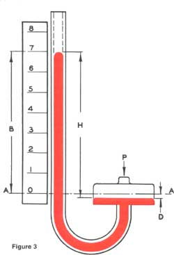
As illustrated in Figure 3, if one leg of the manometer is increased many times in area to that of the other, the volume of fluid displaced will represent very little change of height in the smaller area leg. This condition results in an ideal arrangement whereby it is necessary to read only one convenient scale adjacent to a single indicating tube rather than two in the U-type. The larger area leg is called the "well".
For this reason, the well type lends itself to use of direct reading scales graduated in meaningful units for the process or test variable involved. It does, however, place certain operational requirements not found with the U-type. The higher pressure source being measured must always be connected to the well connection "P". A lower pressure source must always be connected to the top of the tube, and a differential pressure must always have the higher pressure source connected at the well connection "P". In any measurement the source of pressure must be connected in a manner that will cause the indicating fluid to rise in the indicating tube.
The true pressure still follows the principles previously outlined and is measured by the difference between the fluid surfaces. It is apparent that there must be some drop in the well level. This is readily compensated for by spacing the scale graduations in the exact amount required to reflect and correct for this "well drop". By carefully controlling tolerances of the well area and internal diameter of the indicating tube, Meriam well type manometers and scales are manufactured to a high degree of accuracy.
Inclined Tube Manometers
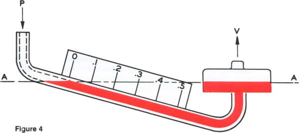
Many applications require accurate measurement of low pressure such as drafts and very low differentials, primarily in air and gas installations. In these applications the manometer is arranged with the indicating tube inclined, as in Figure 4, therefore providing an expanded scale. This arrangement can allow 12" of scale length to represent 1" of vertical liquid height. With scale subdivisions to .01 inches of liquid height, the equivalent pressure of .000360 PSI per division can be read using water as the indicating fluid.
Dual Tube Manometer
In accordance with the manometer principle, it is obvious that the higher the measured pressure, the longer must be the indicating fluid tube. To provide greatest ease in reading high range manometers, Meriam introduced the dual tube manometer which provides for reading full range of the instrument in only 1/2 the total vertical viewing distance.
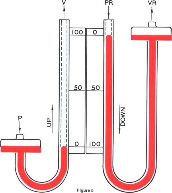
Referring to Figure 5, the manometer consists of two separate manometers in a single case. The left manometer is a conventional well type manometer with well and scale zero at the bottom and scale graduated upward. The right manometer has a well and scale zero raised to the 100" level with the scale graduated downward. Note however, that they are two separate manometers reading the same pressure with one indicating column rising and one falling. The columns pass each other at 50", therefore it becomes convenient to read the left scale on pressures from 0" to 50" progressing upscale and read the right from 50" to 100" coming down scale. Therefore only the lower 50" is required to read the entire 100" range. Here again gauge pressure connections are made at "P" and "PR", vacuum connections at "V" and "VR". The higher differential pressure is made at "P" and "PR" and the lower at "V" and "VR".
Sealed Tube or Absolute Manometer
The term "absolute pressure" is derived from the fact that a perfect vacuum, the complete absence of any gas, is called "absolute" zero. In an absolute pressure manometer the pressure being measured is compared to the vacuum or absolute zero pressure in the sealed tube above the mercury column.
The most common form of sealed tube manometer is the conventional mercury barometer used to measure atmospheric pressure. Such a barometer is a mercury filled tube over 30 inches high immersed in a container of mercury which is exposed to the atmosphere. The mercury column is supported by atmospheric, or barometric pressure.
Some processes, tests and calibrations are based on pressures near or below atmospheric pressure and are most conveniently measured on a sealed tube manometer, referred to as an absolute pressure manometer. These are available in U-type or well type configurations.
Manometer Uses
In addition to straight pressure and vacuum measurement, other process variables that are a function of pressure can be readily measured with a manometer.
Common applications are flow, filter pressure drop, meter calibrations, leak testing and tank liquid level.
Contents of this article were provided courtesy of Meriam Instruments